The EMC standard criteria are currently incredibly difficult to fulfill. This is when Schurter EMC components come in handy.
MIROSLAV PISKOR SOS electronic Product Specialist More articles from the author
Schurter offers a wide range of EMC components
-
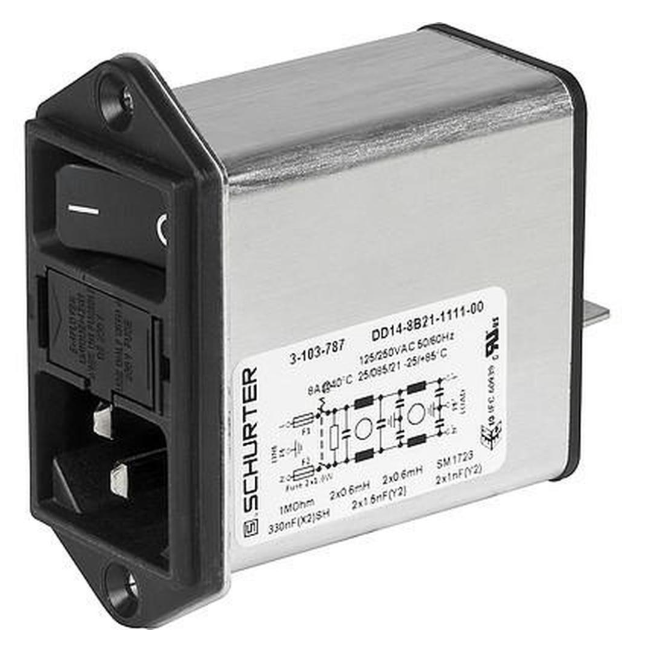
Power entry modules with filter for currents 0.5 to 20A
-
EMC filters (1-phase, 3-phase AC and DC). The smallest one, 1-phase, 6A/250VAC FMLB-09 5500.2031 has dimensions of 50x45x28,6mm and weighs 116g. One of the biggest ones is 3-phase, 1100A/520VAC FMAC-0974-K152I with dimensions of 590x230x200mm and it weighs 47kg.
-
Current compensated chokes (1-phase and 3-phase) for currents 0.4 to 50A.
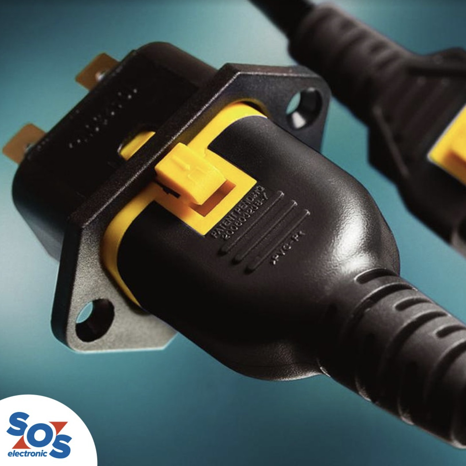
The majority of power entry modules feature V-Lock locking system. The power connector is equipped with a pin that interlocks with a notch in the power entry module and thus reliably prevents the cord from being pulled out unintentionally.
You can find more information about all Schurter EMC components in PEM, filter and chokes overviews.
Why Is a Power Line Filter Necessary?
Currently, electronic equipment typically use switching-mode power supply and fast digital circuit. Such devices generate high-frequency voltages and currents during normal operation. Without the power line filter, it is almost impossible to meet the requirements of the EMC standards.
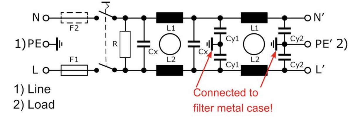
The two primary functions of the power line filter are:
-
Preventing high-frequency signals within the device from reaching the input power line.
-
Preventing high-frequency signals distribution system (disturbance) from entering the equipment.
Currently, information technology equipment (ITE) has to fulfil the requirements of EN55032 emission standard and EN55035 immunity standard.
Limits for conducted disturbance at mains terminals in the frequency range of 150 kHz to 30 MHz and radiated disturbance in the range of 30 MHz to 1GHz are specified in EN55032.
Schurter power line filters are optimized for frequency range 150kHz to 30MHz where they provide the best attenuation but simultaneously, they have also around 20dB attenuation at 400MHz, which helps decrease the radiation from antenna created by power cord.
Conducted emission regulations are intended to control the radiation from the public AC power distribution system, which results from high frequency currents conducted back onto the power line. Normally, these currents are too small to cause interference to other products connected to the same power line, however, they are large enough to cause power line to radiate and possibly become a source of interference, for example to AM radio.
(For example, EN 55032 requires conducted disturbance from Class A devices ≤ 60dBuV = 1mV in the frequency range 500kHz to 30MHz.)
Power-line filter also efficiently attenuates continuous RF disturbances during the test according to EN 55035 §4.2.2.3, where 3V RMS RF signal in range 150kHz to 10MHz, 3 to 1V in range 10MHz to 30MHz and 1V in range 30MHz to 80MHz is injected into power line.
In combination with surge protection, filter also helps to pass tests according to EN 55035 §4.2.4 – electrical fast transient and EN 55035 §4.2.5-surges.
Where Should a Power Line Filter Be Installed?
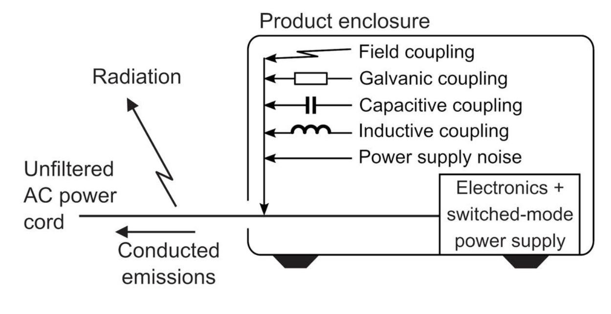
The filter efficiency is equally, if not more dependent on how and where it is mounted, and how the leads are routed to the filter than on the electrical design of the filter. The figure below shows three common problems associated with the mounting of a power-line filter, which significantly decrease its effectiveness.
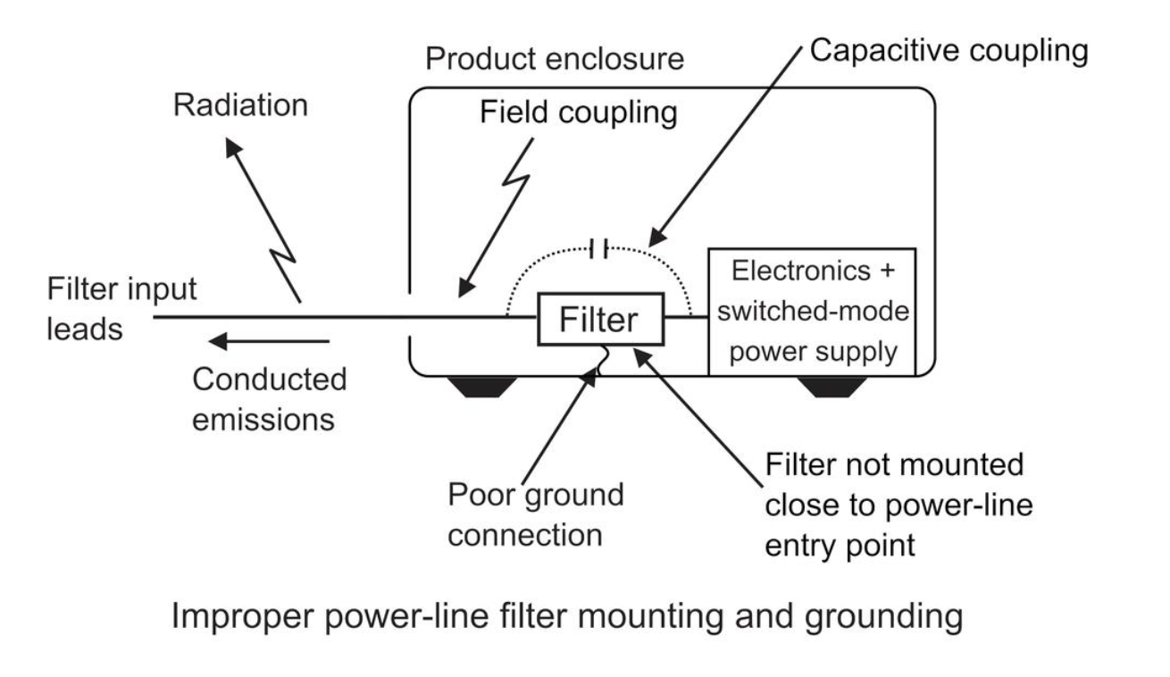
- The filter is not installed close to the enclosure’s entrance for the power line. The exposed power line (antenna) can pick up noise from electric and magnetic fields inside the enclosure.
- The wire grounding the filter to the enclosure has a high inductance, which reduces the effectiveness of the Y-capacitors in the filter. The manufacturer assembles Y-capacitors so that the connection with the cover has minimal inductance.
3.Capacitive coupling takes place between the ac power line and the noisy power-supply-to-filter wiring.
Next figure shows properly mounted power-line filter.
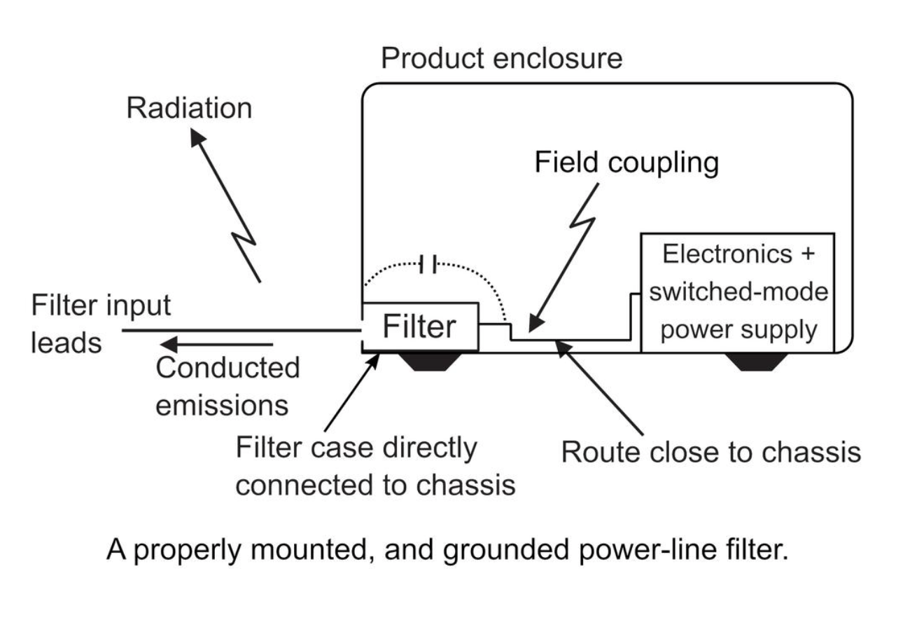
The filter is mounted where the ac power line enters the enclosure to prevent electromagnetic field coupling to the filtered power line. The metal enclosure now also blocks any capacitive coupling from the filter input cable and the filtered power line.
The filter is mounted in a way that the filter’s metal case makes direct contact with the device enclosure, which eliminates any additional inductance in series with the internal Y-capacitors. Any wire between the filter’s case and the enclosure decreases the effectiveness of the filter as a result of its inductance.
The wires between the filter and the power supply should be routed close to the enclosure to minimize any pickup. Do not route the filter’s input leads close to output dc power leads, as this will maximize the parasitic capacitance coupling. Input leads should also be kept away from any signal cables (especially digital cables) and should not be routed over, or near, a digital logic PCB.
An additional improvement over the arrangement shown above is mounting the power supply close to the power line filter.
The above fact points out the advantages of power-line filter having an integral ac power cord connector.
This configuration forces the filter to be mounted where the power cord enters the enclosure and where the filter’s metal flange is screwed or riveted to the enclosure (on an unpainted, conductive surface) so the Y-capacitors will be properly grounded.
For further information about Schurter products, please contact SOS electronic at [email protected]