Everything you need to know about the application of DC-to-DC converters in electronics.
Functions of DC-DC Converters
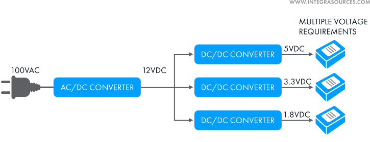
Modern electrical devices have multiple circuits, each of which can require different voltages. To make all systems work properly, you have to either provide each of these circuits with an individual power supply or somehow regulate the output voltage level from a common power source. The latter can be achieved with electric power converters, and particularly with DC-to-DC converters.
DC-DC converters are electronic circuits (or electromechanical devices) that can convert one direct current voltage or power level to another. DC-DC converters have many applications and can be found in almost all electronic devices. They are especially useful for battery-powered portable devices, such as cellphones, laptops, photo and video cameras, etc., but are also used in automotive, computer, communication equipment, and other industries.
Common Types of DC-DC Converters
Linear vs Switching DC-to-DC Converters
In linear converters, the output voltage is reduced with a resistive load, typically a transistor. Such converters are simple and cheap, as they use few components. They are often used in low-power devices with EMI-sensitive circuits or the ones requiring high-quality output voltage and low output voltage ripple.
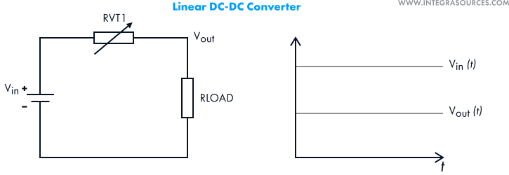
However, linear converters can only reduce voltages. Besides, their efficiency drops as the difference between the input and output voltages rises, which causes overheat issues.
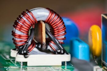
In switching converters, the input current is turned on and off rapidly. The current accumulates in a conductor coil and a capacitor that smoothes the voltage before transferring it to the load. The output voltage level is controlled with the duty cycle of the switching element. Switching DC-DC converters show much higher efficiency (up to 90%) and generate much less heat. Furthermore, different schematics allow you to reduce or raise voltages.
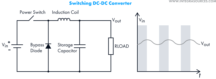
On the other hand, such converters are more expensive and generate more electromagnetic noise.
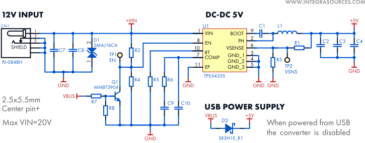
In the picture below, you can see a schematic of a switching DC-DC converter used in a device with a number of radio transmitters. The sub-circuits require 5V, while the input voltage provides 12V and the maximum electric current is expected to reach 2A. It is possible to lower the voltage with a linear converter, but more than half of the energy would be converted into heat. Since the size of the case is only 10x10x1 cm, it’s hardly possible to mount a cooling radiator. Therefore, a TPS54335 switching converter is used instead.
Isolated vs Non-Isolated DC-to-DC Converters
In non-isolated converters, the output and input are connected into a single circuit. As a result, they feature higher efficiency, in addition to being smaller and cheaper. However, there’s a risk of electric shock, so such converters are mostly used in low-power devices.
In isolated converters, the input and output circuits are separated (usually with a transformer), so there’s no direct current flow between the primary and secondary circuits. Such converters are safer, which makes them suitable for high-power devices, and this design allows you to break up ground loops to protect sensitive circuits from noise.
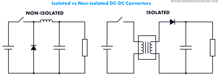
Nevertheless, their efficiency is lower compared to non-isolated converters because the transformer causes energy losses.
Buck DC-DC Converters
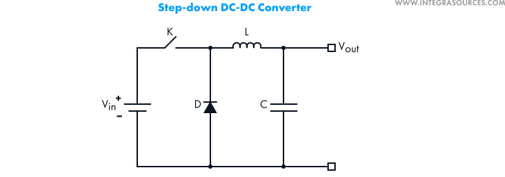
Also called step-down DC-DC converters or choppers, they are used to reduce the input voltage level. A typical chopper uses a conductor coil, a storage capacitor, and a bypass diode to lower the output voltage. Buck converters are typically used in battery chargers, monitors and TV sets, game consoles, and multimedia players.
Boost DC-DC Converters
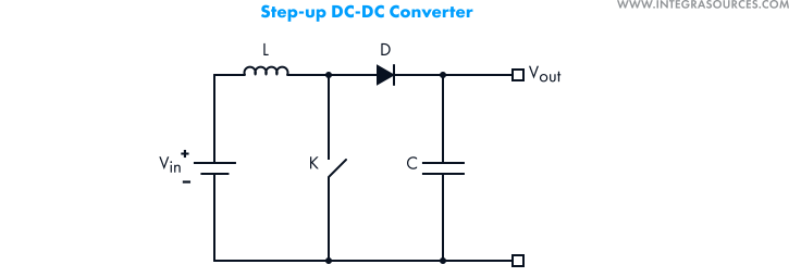
Also called step-up converters, they produce output voltages higher than the input voltage. In a typical boost converter, the induction coil accumulates magnetic field energy, while the closed diode doesn’t let the current flow to the load. When the power key is turned off, the diode is turned on. The input voltage adds to the energy accumulated in the coil, which raises the output voltage.
Boost converters are commonly used in hybrid vehicles, portable lighting devices, in lighting systems with energy-saving lamps, and whenever it’s impossible to provide enough energy with batteries (or there’s no room for the required number of batteries).
Buck-Boost DC-DC Converters
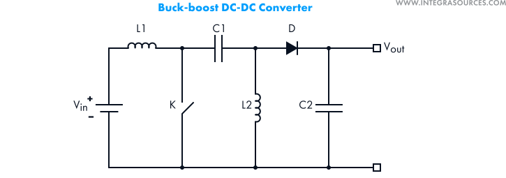
These circuits can produce both higher and lower output voltage levels. They are often used in equipment powered by Li-ion batteries to compensate for the batteries’ voltage drop that happens with time. Buck-boost converters can also be found in cameras, measuring equipment, MP3 players, wireless keyboards and mice, GPS systems, etc.
Inverting DC-DC Converters
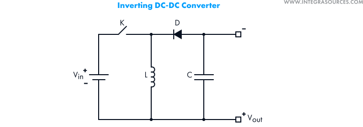
They work just like buck-boost converters but can also invert the output voltage polarity. You can find inverting DC-to-DC converters in devices that require dual supply, such as operational amplifiers.
Major Characteristics of DC-to-DC Converters
Today, you can pick from multiple off-the-shelf DC-to-DC converters to use in your electronics design, but to provide the highest efficiency, one needs to take into consideration the following characteristics of converters.
Output voltage. Obviously, this is the first parameter to consider when choosing a DC-DC converter. Note that some converters can produce adjustable rather than fixed output voltages.
Input voltage. Different converters can only work with a particular input voltage, regardless of their other characteristics. For example, both IK0505SA and IK1205SA DC-DC converters provide the output voltage of 5V and current of 0.05A but have different input voltages – 4.5-5V and 10.8-13.2V respectively. So, if the other characteristics are suitable for your device, the choice will be based on what input voltage you are going to use.
Output current. This parameter defines how much electrical power you can expect from a converter.
Efficiency. It can be described as a percentage of the input power transformed into output. It’s crucial for portable devices powered by batteries. Note that even if efficiency itself is not important in your project, it still must be taken into account, as low efficiency results in overheat issues.

Temperature. Since DC-DC converters are often used in mobile environments, one has to make sure they can withstand certain internal temperatures, which may require additional protection such as a heat sink.
Size & mounting types. Modern electronics designers have to follow two contradictory trends: to make devices smaller and to add as many functions as possible. As a result, size becomes a serious issue in electronics design, so the smaller the converter, the better. One also has to choose from a variety of mounting types.
Supply chain stability. When designing an electronic device, it’s also important to use components that are not going to disappear in the nearest future. That’s why one should pick relatively new models.
Common Regulation Issues
Using DC-to-DC converters can seriously affect whether the device can comply with various regulatory standards, with the most important being electromagnetic compatibility and safety.
Electromagnetic compatibility
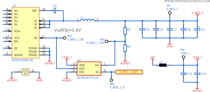
As mentioned above, switching converters provide higher efficiency and generate less heat, which can be found useful in many applications. At the same time, such converters generate electromagnetic noise, which becomes a common problem for electronics engineers. To make sure the device doesn’t cause EMI effects on other equipment and complies with corresponding regulatory standards, you can try different PCB layer stackups, avoid mounting converters near sensitive components, as well as use filter circuits and additional capacitors.
In the following example, a number of components were used to protect an analog sub-circuit from electromagnetic interference: a ferrite bead (L2), four ceramic capacitors (C5-8), and one electrochemical capacitor (C4). The ceramic capacitors suppress the high-frequency noise from the converter, while the electrochemical capacitor smoothes low-frequency fluctuations from different sources. This combination considerably improves the quality of the power supply.
Safety Standards Compliance
Certain DC-DC converters can decrease input voltages by hundreds of volts. If, for some reason, the converter fails, the input voltage can become deadly for operators or patients (in the case of medical devices). Therefore, converters must have sufficient electrical insulation between the primary and secondary circuits.
The IEC 60950-1 standard (and national standards derived from it) distinguishes the following electrical insulation grades:
It is sufficient for the proper functioning of the device but does not provide protection from electric shock in the case of a breakdown or fault. The device is allowed to use DC-DC converters with this insulation grade if:
– The AC-to-DC power supply has reinforced or double insulation between the AC input and DC output;
– The AC-to-DC power supply uses basic or supplementary insulation, while either the primary or secondary circuit of the DC-DC converter connects to protective Earth.
It provides basic protection from electric shock and is allowed if the AC-DC supply uses functional insulation, while the output circuit of the DC-DC converter connects to protective Earth.
It must meet all the requirements for basic insulation and also use one more protection level, such as increasing the distance through insulation by 0.4 mm for peak voltages above 71V. This grade is required if the AC-DC supply uses basic insulation.
Protection grade is considered to be double insulation if it combines basic and supplementary grades.
It provides the same level of protection as double insulation but is designed as a single system, using several protection layers. It is required if the AC-DC supply has no insulation or functional insulation.
Thermal Insulation
As mentioned above, certain types of DC-DC converters cause overheating, which becomes an even greater problem in mobile environments. That’s why it’s important to solve this issue at the early stages of electronics development.
Even if the converter’s maximum full-power temperature remains within the norm, it doesn’t mean the device will comply with various safety standards (for example, EN60950-1 and UL60950-1). Most DC-DC converters use planar transformers (most heat comes from transformers) that are not regarded to be safety hazards as long as their temperature doesn’t exceed the maximum rating of the printed wiring board.
Standards usually require class B or F thermal insulation systems for transformers (that are considered safe if the temperature doesn’t exceed +130 °C and +155 °C, respectively).
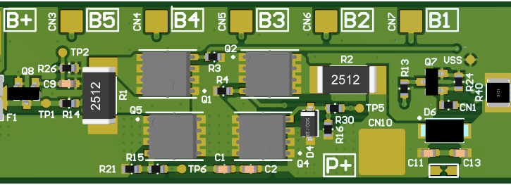
Often, electronics designers use a combination of methods to solve overheating problems. The image below shows four converters. Here, the heat dissipation problem was solved by using MOSFET transistors with a lower static drain-to-source on-resistance, as well as parallel traces going through all four layers of the printed circuit board. Additionally, the PCB has plenty of vias to dissipate heat from both sides.
Some Common Mistakes in DC-to-DC Converters Design
In most cases, electronics designers would use off-the-self converters for their projects, but sometimes, the team may need to design their own DC-DC converter. These are some of the common mistakes that can occur. You can read more about it in this Texas Instrument’s seminar proceedings.
1. Wrong inductor
The choice of inductors defines the converter’s efficiency, control loop stability, and transient response. Using the wrong inductor can lead to various problems. For example, an inductor made from hard saturating magnetic materials that operates above its saturation current limit will show significant permeability decrease. In this case, you will see a peaking inductor current waveform.
Picking an inductor with the right inductance value is also important. If this parameter happens to be too low, it will lead to significant core loss, resulting in fast overheating.
2. Wrong soft start time
Large output capacitance, a short circuited output and/or a heavy load during start up can result in the converter not starting up. The output voltage would rise, but then the converter would suddenly stop. It happens when the soft start up time is too fast. In this case, the input voltage sags, which triggers overcurrent protection. Programming the right soft start up time will fix this issue.
3. Mistakes in PCB component placement
Input decoupling capacitors must be placed next to the converter. Otherwise, the switching node (usually a power MOSFET) would start exhibiting large ringing. It will increase power loss, create more electromagnetic interference, cause more stress to the converter, and can potentially damage the circuitry. PCB design is also important for the thermal performance of an IC: wrong component placement can cause certain parts to not work properly or the IC’s lifetime to decrease.
Finding suitable DC-to-DC converters and avoiding these and other mistakes at the same time is a challenging task. One has to take into account a range of factors, anticipate potential issues, and try to make the design as cheap as possible to ensure commercial viability of the project. Integra Sources is an experienced team of hardware and software developers with over 250 successful projects under our belt, including electronics design, power electronics development, robotics, and many more.
To learn more about DC-to-DC converters and their applications, you may read another article on the topic on Integra Sources’ blog.