In the future, autonomous driving will maximize the convenience of mobility. Until that time, many small electrical drives enable easier, more convenient control of the vehicle. But how are they constructed, what requirements do they need to fulfill, and which applications can manufacturers provide to make driving even more pleasurable for their customers?
Today, there are over 75 small electrical drives in a mid-size vehicle, and that number is increasing. Electric motors with up to 100W in power handle functions such as adjusting the side mirrors or closing the trunk door. Other automatic adjustment mechanisms are also possible depending on the user conditions, including not only the seats but also the interior mirrors and headrests, for example, or even gesture-controlled compartment doors, perhaps to open and close the glovebox.
As small drives are based on the 12V on-board voltage, they can be powered directly via terminal 30 (battery) or terminal 15 (post-ignition). They are partly the reason why the 12V electrical system will not be disappearing from the vehicles of the future – switching to the increasingly popular 48V technology at this power level would not yet offer any significant benefits right now in terms of lower production and development costs. However, looking at the lower wire cross sections and nominal load currents of a 48V electrical system, which are just a quarter of those of a 12V system, these are arguments that need to be considered in the long run.
In drives of up to 100W, brushed DC (BDC) and brushless DC motors (BLDC) as well as stepper motors are used. The latter are ideal for applications where absolute precision control is required or very fine step adjustments need to be performed, for example for adjusting the mirrors and moving the dashboard needles. BDC motors are used wherever long service lives and higher efficiency can give way to cost benefits. BLDC motors are the most robust versions, but they are more expensive and sometimes more complex to control.
Construction and Function of Controller
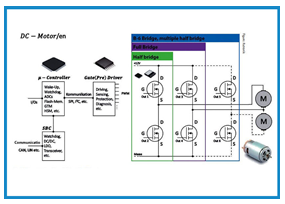
Figure 1 shows a simplified circuit design of a small drive with DC motors, featuring the main components: the microcontroller, the system basis chip (SBC), the MOSFET driver (gate driver) and several MOSFETs. The SBC is used to create a communication interface with the vehicle bus, ensure that the key components are suitably supplied with power, and can perform tasks in the interest of functional safety and reliability (a watchdog function, for example). Each of the MOSFETs are arranged as half-bridges, forming a full bridge (also known as an H-bridge) together with the motor connected between them. Adding another third half-bridge creates a B6 configuration that allows two DC motors (as shown in Figure 1) or a three-phase BLDC motor to be controlled.
The microcontroller receives the input controller signals via its I/O pins and processes them to control the gate driver. At the same time, it can evaluate the signals of the driver when an error occurs. The MOSFETs are triggered by the driver using a PWM signal.
This full-bridge/B6 arrangement can turn the motor clockwise or anticlockwise.
Controlling BDC Motors…
BDC motors fundamentally consist of the rotor, the commutator with carbon brushes, and the stator (or permanent magnet). The carbon brushes conduct the current to the rotor. The friction that this generates causes the brushes to wear down. The rotary movement is generated by the rotor’s magnetic field forming as a result of the current passing through the rotor. The rotor’s magnetic field is aligned with that of the stator. Once the opposite pole of the stator’s magnetic field has been reached, the commutator installed in the rotor changes the magnetic field of the rotor and generates a magnetic field that is inverted by 180°. This causes the two identical poles to repel each other and the rotor pole is drawn by the opposite stator pole. The commutation is therefore a purely mechanical process. There is no need to determine the position of the rotor during start-up.
…BLDC Motors…
BLDC motors are constructed like AC synchronous motors and have a purely electronic commutation mechanism, with permanent magnets in the rotor and a controllable winding in the stator. The windings are usually arranged at 120° angles to one another (or divisible fractions of these) and are stimulated in sequence, depending on the direction of rotation. The rotor follows this rotating magnetic field.
To prevent excess load caused by high start-up currents, the rotor position should be determined before start-up to ensure that the right winding is activated during start-up.
With sensor-based position detection, three Hall Effect sensors precisely detect the magnetic field of the rotor’s permanent magnet. This method results in higher component costs and requires more space and wiring, but is simple to create. Appropriate automotive-qualified (AEC-Q100) Hall Effect sensors from Diodes, Melexis and TDK-Micronas are available from Rutronik.
FOC (Field Oriented Control) is a popular sensorless method, even if the implementation of the software algorithm and the management of the motor size transformation are complex.
With the TLE9879 three-phase embedded motor driver (e-power IC), including eval kit and FOC example algorithms, Infineon has provided an answer for sensorless BLDC control via FOC. The high level of integration of the IC means that only the B6 bridge and the motor are otherwise needed.
…and Stepper Motors
Stepper motors only have windings in the stator. They are usually constructed as hybrid stepper motors, where the rotor construction’s defining feature is a permanent magnet combined with a soft iron core. Selective triggering of the windings allows the rotor to be adjusted by a specific angle. The angle change in each step depends on the number of phases of the motor and the number of pole pairs in the rotor; the angle change is usually 1.8° or 0.9° with two phases (i.e. there are two windings in the stator and a corresponding number of poles in the rotor core). The stepper motor is relatively simple to control; it enables reproducible movements and very high precision. And furthermore, it doesn’t require any position feedback.
Requirements of Small Drives
Depending on the application, small electrical drives need to fulfill a variety of requirements. The most important ones are:
High efficiency
Low size and weight
Low noise emissions and silent running
Resistance to stresses (water, dust, vibration, etc.)
Different operating modes (continuous operation, periodical operation, brief operation)
High reliability, especially with safety-critical drives
Low costs
Ease of implementation
Semiconductor suppliers are addressing these requirements with ICs specially enhanced for these purposes. For example, Toshiba’s TB9083FTG is designed specifically for functional safety applications as a fail-safe pre-driver. Optimizations in process technology enable smaller packages and the use of less material, for example with the MOSFETs from Diodes (PowerDI3333-8) with a package size of around 3mm × 3mm at 40V. Reduced bias currents in drivers and a lower switch-on resistance (RDSon) in the MOSFETs increase efficiency, which reduces power loss and heat output. New packaging technologies with top-side cooling and increased heat dissipation contribute to simpler heat management, which increases the resilience of the IC. To minimize noise emissions and EMI problems, all suppliers implement functions such as PWN and slew rate control depending on the drivers.
More and more system-related functions are integrated into the semiconductor modules to facilitate implementation in the circuit. This includes current measurement and integrated current amplifiers (CSA) as well as protection and diagnostic functions such as data import via SPI for easier status detection and end-of-life estimation. Functions such as auto-restart and latch-off also allow for testing and restart after an error. Suppliers also provide simulation tools such as Infineon’s “Toolbox” to help developers with implementation.
Different Integration Levels for Different Requirements
Depending on the requirements, chips with different integration levels are available to choose from (see table).
In a discrete design, each circuit component is positioned on the PCB. This is often the cheapest option, but it needs plenty of space and results in higher ambient temperatures. To keep space requirements as low as possible, Diodes offers a broad range of dual MOSFETs (N-type) and complementary MOSFETs (N+P-type) in a single package. When it comes to discrete drivers, superb products are available in the form of Infineon’s TLE9180; these can be used with a variety of electrical system voltages, and so are also suitable for small control applications in the truck segment.
For medium integration applications, some components have been combined into modules. These may consist of MOSFETs and the associated drivers, such as Rohm’s BD63035EFV-M or Bosch AE’s CJ260. Infineon on the other hand combines SBCs (system basis chips) with the drivers in its TLE956x modules. Medium integration offers a good compromise between space and cost restrictions. It requires the least development effort and is currently the best way to implement circuit protection. But if construction space is very limited and PCB cooling can also be achieved with difficulty, it is recommended to take another step towards integration.
High integration combines the microcontroller with the MOSFET driver and the functions of an SBC in a single package. But this usually also makes it very inflexible as the only way left to make any adjustments is triggering the MOSFETs. This highly integrated component comes from Infineon and is known as the “E-Power IC” (TLE98xy). Infineon compensates for the lack of flexibility with a variety of IC models for applications with half, full or B6 bridge requirements.
TDK-Micronas’ HVC4223 embedded motor controller is representative of the highest level of integration. It combines all four components – microcontroller, SBC, gate driver and MOSFETs – in a single IC, but this also means that it needs to fit the requirements of the application exactly.
The benefit of the medium and high-integration modules is the integrated diagnostic features. These usually include
OC/UC – over/undercurrent protection
OT – overtemperature protection
OL – open-load protection
SC/SCG – short circuit/short circuit to ground protection
LD – load dump protection
Cross-conduction protection
Reverse polarity protection (usually via external MOSFET)
Discrete MOSFET drivers with protection and diagnostic functions are now also offered, for example with overcurrent and overtemperature protection, although additional discrete components such as PTC thermistors (positive temperature coefficient thermistors) are often necessary here.
The protection and diagnostic features are currently becoming an essential aspect for electronics developers and OEMs because they allow for easy circuit monitoring. As such, they also represent a step towards fully autonomous self-monitoring vehicles.