
In SOS electronic, we played with Sensirion and Bridgetek development kits, which we connected to the air quality measurement kit. However, the Arduino module can do much more, see for yourself.
We will focus on practical demonstration of NerO development board, CleO35 3.5“ display, and sensor shield ESS-SGP30-SHTC1.
Assembling is easy, just click CleO35 on the bottom side header side of NerO and sensor shield on the top side, connect the power supply and we are ready to go.
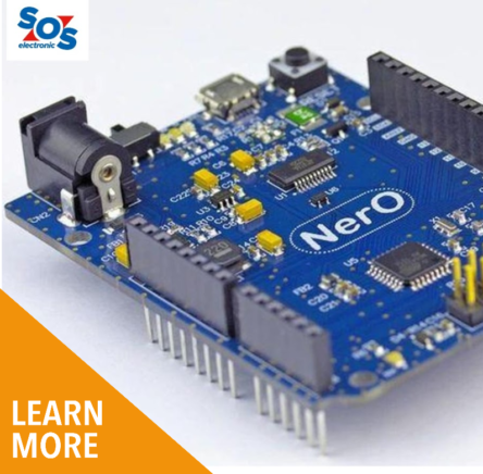
NerO Development Board:
Basically it is a clone of well-known Arduino UNO from Bridgetek with two improvements:
- The linear voltage regulator was replaced by a switching regulator
- Board contains male header for CleO displays and standard female header for Arduino shield
- FT231XS is used as UART/USB converter
- Board uses micro-USB connector and has a power switch
The board is fully compatible with Arduino IDE, which was used to write a demo program. You can find more information on our website.
TFT Display CleO35:
At first glance, the Cleo35 is just another 3.5” TFT display with a resolution of 480×320 pixels and a resistive touch panel. CleO35 offers much more:
- FT810 Advanced Embedded Video Engine (EVE2) that does most of the imaging work, including short video playback, so it’s easy to operate even with less powerful processors like the NerO board – ATMega328AU
- FT903 32-bit RISC microcontroller that communicates with the NerO board via SPI while allowing the use of the camera, microSD card, 8MB flash, audio playback, and additional UART and SPI interfaces.
If you need a larger display you can use the 5“ 800×480 CleO50.
Sensirion Arduino Shield ESS-SGP30-SHTC1:
The last module in our assembly is Sensirion Arduino shield with two sensors:
- SHTC1, relative humidity, and temperature sensor
- SGP30, that measures VOC concentration in range 0 to 60 000 ppb and H2, from which it calculates the equivalent concentration of CO2eq in range 400-60000 ppm.
In addition to the sensors, it also includes a 1.8V voltage regulator for SGP30 and SHTC1 power supply and a 1.8V/Arduino_VDD I2C level converter. Note also the location of the SHTC1 sensor; it is located on the PCB as far as possible from other components that could affect the measurement accuracy by their radiating heat (especially the voltage regulator).
The manufacturer also recommends the correct adjustment of the airflow around the sensors so that the airflow first comes to the SHTC1 sensor and then continues to the SGP30 sensor.
Technical parameters of assembly:
- Power supply voltage: 12V/DC
- Display: 3,5“ with resistive touch panel
- Measured values: CO2eq (calculated from measured H2 concentration), TVOC (total volatile organic compound), Temperature, Relative Humidity, Dew point (calculated from RH and Temp)
- Outputs: measured values/graph are shown on display and sent through USB (virtual serial port) to PC
The introduction is over. The following pictures show the whole assembly running:
Programming of NerO Board:
The first step is to load the firmware into the NerO board. To do this, we need to install the Arduino IDE development environment on your computer. Firmware was written in version 1.8.9. To compile and load the source code, we still need to download and install the necessary libraries into the IDE, which will simplify the work with the modules used.
First of all, we need a library for the CleO35 display, which you can download, including other tools, from the manufacturer’s website. CleO_1.1.2 includes the Arduino Libraries folder. We copy it to the libraries folder of the Arduino IDE. We also need a library for sensor operation from Sensirion, arduino-ess. Again, we copy it to the libraries folder in the Arduino IDE. Now we can load the Nero-Cleo35_ESS.ino project into the Arduino IDE and program NerO board. Connect our assembly via USB to the PC, select Arduino UNO in the board settings, select the appropriate COM port and press the Upload button to load the firmware into the NerO board.
The measured values will appear on the display after the restart. Then touch anywhere on the display to toggle between graph and value display and back. At the same time, all measured data is sent via the virtual serial port to the PC where it can be captured, for example by the TeraTerm terminal emulator.
Of course, this is just a small demonstration of what these modules can do. The installed libraries also include demonstration projects and even entire skeleton that need to be only slightly modified to exactly match your requirements. At the same time, it is an excellent learning kit for those of you who want to learn to program on the widely used Arduino platform.
All used products in this kit can be found in our offer available directly from our stock or by order.
For more information about the product or article, please contact SOS electronic at [email protected]