The DC link capacitors are powered when switching on the DC link of frequency converters. The resulting inrush current must be limited here. Ralf Hickl, Product Sales Manager Automotive Business Unit, and Uwe Rahn, Director Automotive Business Unit, at Rutronik explain how this can be achieved with high-voltage switches.
Rated voltages of up to 1kV in the DC link of the traction inverter are currently being discussed for electric and hybrid vehicles. In their application notes and reference designs, the suppliers of engine inverter IGBTs or MOSFETs specify low-inductance filter capacities that must be connected parallel to the half-bridges of the power output stage. In its reference design, for example, Infineon recommends a filter capacitor with values of 300µF/450V for traction inverters for a power module in the HybridPack™1 package. When charged to its rated voltage, it has around 30W of energy. Such power film capacitors are currently available from, e.g., AVX, Rubycon, and WIMA.
In terms of energy efficiency, the electrical connection between the HV battery and the inverter should be kept as short and as low resistive as possible. While for reasons of safety, the battery and the traction inverter are electrically isolated by contactors when the vehicle is switched off. Therefore, precautionary measures have to be taken when switching on the contactors to limit the charging current in the initially discharged filter capacitor. To guarantee regenerative braking with regenerative operation of the traction inverter, the main contactors must be designed for bidirectional current flow. In this respect, it is important that the current can be switched on and off in both directions.
With electromechanical switching contacts the principle is fully implemented, but additional expenditure is required when using MOSFETs as semiconductor switches. The reason for this is that, parallel to the drain source path, a parasitic body diode can be found on the chip of these components. The current flow via this diode cannot be switched off.
Therefore two MOSFETs need to be connected back-to-back in series to disconnect the bidirectional current flow. While just one is sufficient for IGBTs without an integrated fast recovery diode (FRD).
Pre-charging technology of capacitors in DC links
The suppliers of industrial frequency converters have long been familiar with this topic and have developed various methods for charging DC link capacitors. One of them is pre-charging via a charging resistor (Fig. 1).
This functions as follows:
The main relay 2 is connected to the negative path load-free.
The DC link capacitors are charged via the pre-charging contactor. The system is limited to a certain current by the pre-charging resistor.
And the pre-charging contactor remains closed until the capacitor is almost fully charged and the voltage is above a certain percentage of the rated voltage.
The main contactor 1 is switched on. Accordingly, the main contactor 1 only has to transmit an inrush current with far less energy than would be the case without pre-charging.
The pre-charging process can take several hundred milliseconds. It demands that the load is high-resistance and that the inverter is off. If this is not the case, the capacitor cannot be fully pre-charged as the load together with the pre-charging resistor represents a voltage divider. Then just a fraction of the rated voltage goes via the capacitor.
A number of measures are recommended here for safety reasons:
Limitation of pre-charging duration to prevent the pre-charging resistor from overheating, particularly with inverter faults which could result in a load current in the DC link.
Temperature monitoring of the pre-resistor with a switch-off function in the event of excess temperatures in order to protect the resistor from repeated unsuccessful charging attempts.
Monitoring of the DC link voltage while pre-charging with connection of the main relay only after reaching a threshold. This limits the inrush current, protects the main relay and prevents upstream fuses from being tripped.
Pre-charging of the DC link with semiconductor switches
ROHM offers the RGSxxTS65HDR range, the second generation of Field Stop Trench IGBTs with built-in FRD for up to 650V in series. They feature the following properties:
Qualified to AEC-Q101
Low collector-emitter saturation voltage,VCE(sat)(type) of 1.65V
Short-circuit proof for at least 8µs
Low switching losses
Reduced gate loading
TO-247N package
Types up to 1200V are already available from ROHM as samples.
To ensure recuperation does not occur via the charging resistor, a power diode must – in addition to the IGBTs with built-in FRD – be connected back-to-back in series with the FRD.
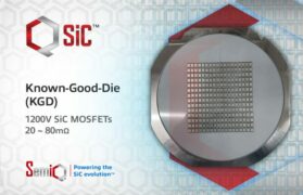
SiC MOSFETs
MOSFET Dice made of silicon carbide (SiC) are characterized by their:
Temperature stability
Dielectric strength
High switching frequencies
Very low switching losses
ROHM is one of the few suppliers of this kind of SiC wafers in the world. The SiC MOSFETs are available for 650V, 1200V and 1700V, ROHM is currently developing the third component generation and is qualifying a number of second-generation types for 1200V for use in cars.
To avoid recuperation via the charging resistor, MOSFET semiconductor charging contactors additionally feature a power diode in the current path.
Insulated automotive gate drivers for MOSFETs and IGBTs
High-side n-Channel MOSFET or NPN IGBT switches require a gate control voltage above the positive voltage to be switched. Insulated gate drivers with an integrated charging pump or with boost converters deliver corresponding voltages and the driving powers for charging and discharging the gate source capacity.
They also come with protective functions with a corresponding signal output on the low-voltage side, e.g., to prevent overcurrent and/or desaturation, the Miller effect and excess temperature. Further advantages are short signal throughput times and soft turn-off.
An example of such a complex insulated gate driver is ROHM’s BM6104. This single-channel gate driver for MOSFETs and IGBTs offers an insulation strength of 2500Vrms, a short throughput time of 150ns at a minimum pulse duration of 90ns. It is qualified according to the AEC-Q100 standard.
Conclusion
When pre-charging the DC link capacitors of an inverter with DC link via a resistor, the pre-charging contactor can be designed as a wear-free semiconductor version.
Find components at www.rutronik24.com.