We often hear about damaged parts due to high temperatures, overheated joints, or the short lifetime of tips and soldering handles. Do you struggle with the same problems? Then this article is for you, we bring you answers to your doubts and questions about soldering.
At a first look, hand soldering is an easy operation. And basically, it is true, a person with short training is able to make nice and good connections.
But those of you who solder on a daily basis know that it is almost a masterpiece to make a reliable and visually appealing joint.
A reliable connection is crucial at all stages of the project. Whether it is a prototype, a pre-production series, or a run-in production.
What is a soldered joint?
It is an electrically conductive connection of two wires, surfaces, outlets, etc. with the use of molten metal. This connection, in most cases, also has a fastening function – it mechanically fixes the component or conductor. And therefore the components, except those operating at a high vibration, no longer require additional support.
Without a deep penetration into chemistry or metallurgy, we can conclude that molten solder (colloidal tin) forms an intermetallic transition layer that contains elements of the solder itself, as well as elements contained in the soldered surface, most often copper.
Solder
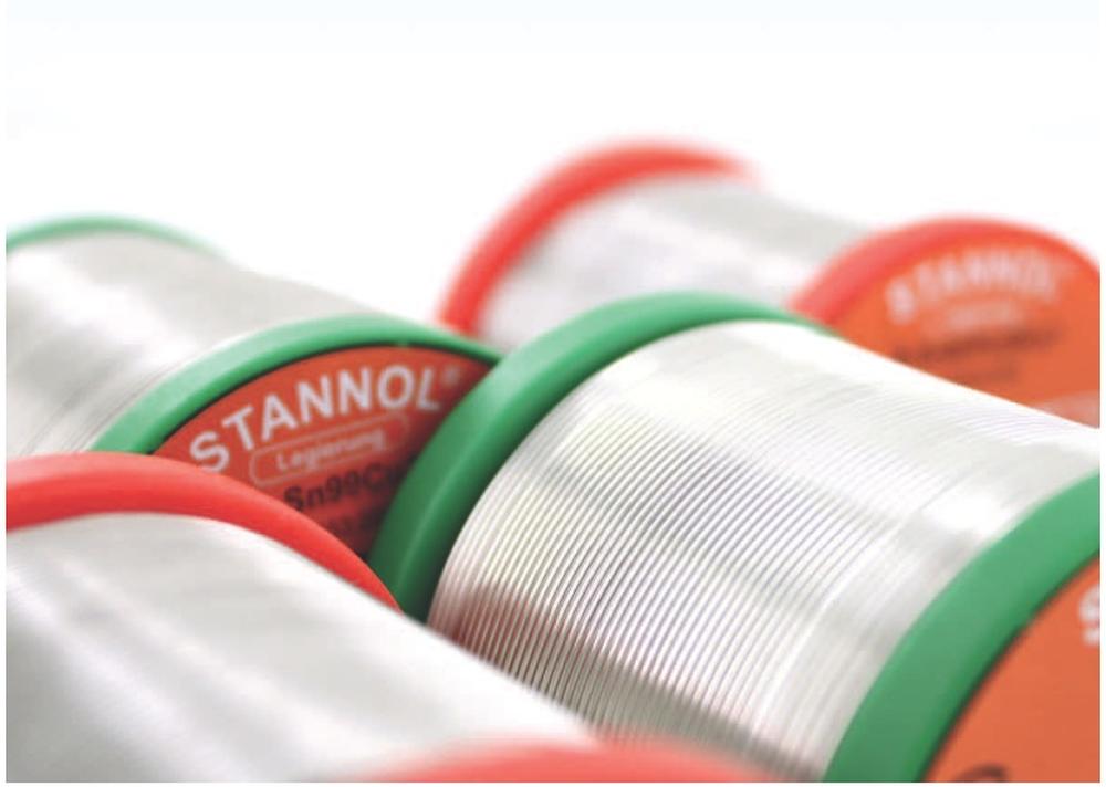
We recognize two types of solders – soft and hard. But don´t get confused by this division, because it is not about mechanical softness/hardness. The difference between them is the melting temperature. The melting point of the soft solder is below 500 °C. Soft soldering is used in electronics almost exclusively.
Soft solders are always made up of two or three main metals and some additives. In a very small proportion, they also contain different micro-alloying ingredients which are usually hidden by the manufacturer, as they are part of the manufacturing know-how and often have a significant influence on the behavior of the solder.
Even though common lead, as well as lead-free solder, has worse electrical conductivity than copper, in practice, it is usually not necessary to take this factor into consideration apart from devices that operate with extremely high currents.
Tin/lead (SnPb) solders were widely used for many decades, most often in a ratio of 60:40 or Sn63Pb37, and a small amount of additional metals such as copper and other micro-alloying ingredients.
Lead has one major and well-known drawback – it is a toxic heavy metal, that accumulates in the body, attacking the nerve system, reproductive organs, etc. So, after the adoption of the directive, known as RoHS, lead has been abandoned (it is used only in medicine, military, and automotive sectors).
Although the transition to lead-free technology has brought technological complications, it has been a very good environmental step overall.
Why are there complications with “lead-free”?
The working temperature is about 20-30 °C higher. At the same time, the mechanical and optical properties of the joints were not always ideal at the beginning. However, the technological attributes of lead-free solders have significantly improved over the past decade, and both the reliability and appearance of joints are mostly at a very good level. The biggest technological minus, which will not be overcome very soon, is the higher melting temperature and hence the higher thermal stress of the components during soldering.
Manufacturers of components have also adapted. It is no longer a problem to find, for example, SMD connectors that use modern high-temperature plastics that resist reflow at such elevated temperatures these days.
How is it with melting temperature and why do tin-based solders, but without lead, have the temperature usually higher?
Well, it’s very interesting. Alloys used for soldering have a lower melting point than the elements from which the alloy is composed. For example, pure lead has a melting point of 328 ° C and a tin of 231.9 ° C. However, the Sn63Pb37 alloy has a melting point of only 183 ° C (!).
The common and known lead-free alloy Sn96.5Ag3Cu0.5 (so-called SAC305) has a melting point of 217-218 ° C, thus apparently the positive effect of lead in the alloy which reduces the melting temperature is missing. For those looking for an explanation of this phenomenon, we recommend entering the words “eutectic” and “phase diagram of metals” in the search engine.
Why is the melting temperature sometimes referred to as an interval rather than a single specific value?
If, for example, we find the melting point of 183-190 °C in the table for the Sn60Pb40 alloy, it means that even at temperatures as low as 183 °C, the metal appears to be liquid, but there is one large BUT – there is still a significant proportion of undissolved crystals. The whole metal dissolves only after heating above 190 °C and it is essentially the minimal temperature that the brazed joint should achieve in order for the resulting bond to have the desired quality. Only with so-called eutectic alloy (metal ratio) is this interval so narrow that the melting range is essentially one temperature (not an interval).
This usually wider melting interval is one of the factors that can affect the formation of the so-called cold joints with worse conductivity. The operator might think that the solder joint is already melted but in fact it may not have melted for 100%. Fortunately, the temperatures commonly used in manual soldering in practice are significantly higher than the melting temperature of the solder. Therefore, this risk appears only for joints that conduct heat very much.
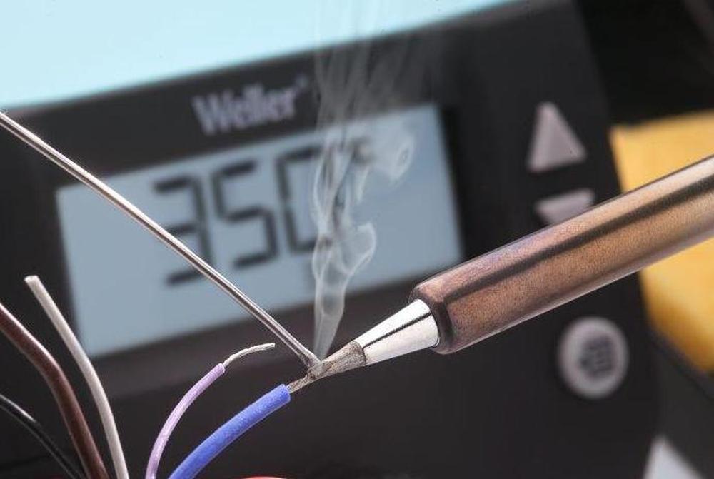
Flux or why do solder fumes during soldering?
Maybe some of you have an experience with a flux-free solder wire. If you tried to solder it, the result was probably more than bad.
There is almost each time at least a microscopic oxidized layer on the metal surface which prevents the good melting of the solder. Even if the joint is perfectly clean before soldering, and the soldering temperature is the same as always, a thin oxide layer is formed almost immediately. At the same time, the solder is also being partially oxidized, producing slag which further deteriorates the bonding properties.
What are the main tasks of the flux which is part of almost every solder wire? to remove the tiny oxide layer, prevent oxidation during soldering and ensure the best wettability.
Historically, the main and still frequently used main constituent of flux is rosin;this substance is obtained from the coniferous tree’s resin.
A colophony is a natural material, with a relatively pleasant aroma. Colophony solder residues are not corrosive and may remain on a PCB. However, during soldering, the colophony is fairly smoke-rich and its residues are only harmless in a relatively dry environment. In a humid environment, they are subject to hydrolysis and can be slightly corrosive.
Manufacturers have gradually come up with many other modified colophony-based fluxes but also based on different resins or fully synthetic compounds. Colophony-based fluxes are still popular, but many synthetic fluxes have overcome the attributes of colophony-based fluxes.
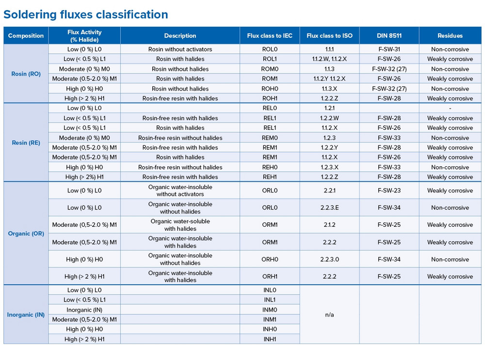
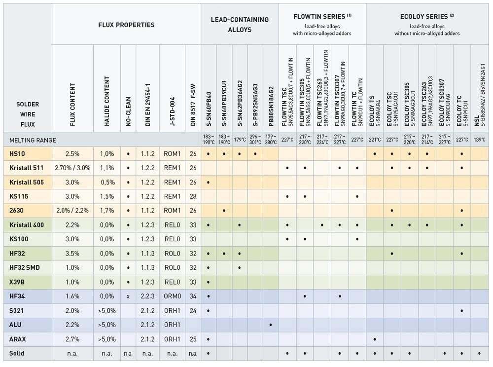
We can find the exact flux specification in the technical sheet of flux or solder wire that the flux contains and is practically always described either according to DIN EN 29454-1 (eg type 1.1.2), J-STD-004 (eg ROM1) or according to DIN 8517 (eg F-SW26) standard. In this example, type 1.1.2. roughly corresponds to type ROM1 or also F-SW26.
The most common types of fluxes for soft soldering
To have a better idea, we also prepared for you a table of the most commonly used types of fluxes according to standards J-STD-004, as well as DIN 8517 and their basic features.
Where do we come across the fluxes?
Fluxes are typically contained in the solder wire in the range of about 1-3.5%. Of course, they are also available separately in liquid or gel/paste form suitable especially for repairs.
Liquid fluxes are mainly used in wave soldering. In the usual manual soldering, adding a few THT components on a board already equipped with SMT components, the flux is usually not required as it is already contained in the solder wire.
It is worth mentioning that many fluxes also contain halides, especially those designed to solder not completely clean surfaces and to solder thicker joints (e.g. motor terminals, alternators, etc.). Halides have considerable “cleansing” and wetting properties, but at higher concentrations, they can be corrosive, hence the halide content is always easily identifiable from the classification of the flux.
Fluxes normally have different market names, e.g. HS10, KRISTALL 400, TELECORE HF 850, etc. From the point of view of an effect and attributes, there may be considerable differences between fluxes of the same classification but from different manufacturers. You can read more about the fluxes and their labeling on our website in the article “Find the Right solder for you”.
How is the flux information reflected in the solder name?
The full name of the solder wire always consists of the (commercial) flux name, the alloy composition, and the percentage of flux, such as KRISTALL 400 Sn96.5Ag3Cu0.5, 2.2%
Are all soldering wires spattering in the same way?
As we know, the hand-soldered PCB is usually contaminated with flux residues contained in the solder wire, as many fluxes are spattering several centimeters around the joint. However, there are already various types with low spatter fluxes on the market. “Low spatter”, low smoke, as well as a small amount of translucent and non-tacky residues. You might have heard about for example Kristall 400, Kristall 511, Trilence, Telecore HF 850 and others.
Now we have a suitable solder so let’s solder
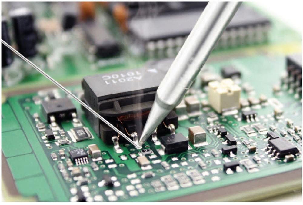
Suitable solder and clean (non-oxidized) surfaces (component outlets) are essential prerequisites for good connections. Of course, there is still a technological “minimum” that we should follow to get the perfect result.
Soldering station
In principle, it is enough to rely on the tip having the temperature that we have set with as little deviation as possible. At the same time, the heat transfer from the heater to the tip should be as good as possible. In practice, these seemingly simple requirements are fulfilled only by quality solders from renowned manufacturers. Satisfying heat transfer to the tip and then to the soldered joint is really quite a challenge.
Why is it often so difficult to overheat a connection, even though the display shows 380’C , which is about 150’C more than the lead-free solder temperature?
You probably know the answer – it is because of low power, or more often because of the insufficient heat transfer from the heating element to the tip and then the joint. The copper area around the joint, perforated holes, PCB material, outlets are all the mass that the tip must heat over the solder melting temperature and, moreover, they are like miniature coolers, with fairly good heat dissipation during soldering.
We can not influence the heat transfer from the heater to the tip, but a proper choice of soldering station and its handle may help. Every reliable manufacturer, such as in our company well-proven Weller, offers a comparison of its models and the selection table according to the size of joints.
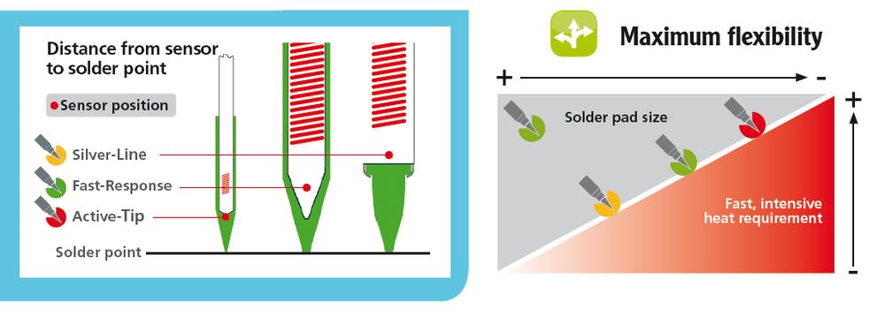
On the other hand we can influence the choice of the right tip. In principle, the tip should be approximately as large as the soldered joint. In other words, it should be as large as we are able to use for a given joint. The better the heat transfer from the heater to the tip, the lower the temperature can be used.
From a physical point of view, the best heat conducting features are at the short and thick tip. Of course, the pike itself can be relatively thin, so it can be easily used e.g. to solder 0603 or 0402 SMT parts.
From a constructional point of view, a construction in which the heating element together with the temperature sensor are integrated directly into the tip has the ideal heat transfer from the heating element to the tip. They thus form one whole, the so-called “cartridge”, or as Weller defines it- “active tip”.
This design allows even relatively small tips to have a large real power transferred to the joint. You can read more about it in our article.
This is perhaps the most important rule when choosing a soldering tip. Practice shows that usually, the best choice is a short conical tip with a relatively thin flat chisel-shaped pike. An example of such a tip is, for example, type LT A.
Why is it preferable not to bake the tip too much?
As you know, even the same sized joints have a significantly different heat requirement. Usually, the worst are ground connections with a large copper surface around, with plated through-hole connections (so-called vias), especially in multilayer boards.
Thin and long tips usually do not help in such cases, because they cannot bring enough heat for demanding joints. Therefore, the operator often “helps” himself by setting a high temperature. Temperatures above 380-400 °C are considered high for long-term soldering. At these temperatures, the tip and solder on the tip oxidize very quickly, needs to be cleaned relatively often, and the life of the tip, as well as the heater in the handle, is significantly shortened.
At the same time, if the operator wants to “make life easier and to increase productivity”, and he solders larger THT joints as well as miniature SMD components (with the same tip) without changing the tip temperature, small connections with little heat demand are exposed to unnecessary high-temperature shock.
In contrast, the thicker and shorter tip, along with the good heat transfer technology from the heater to the tip, allow the temperature of 330-360 °C (sometimes lower) to be used for the same joints, while the lifetime of the tips and heater is significantly higher. The tip does not oxidize so quickly, so we do not need to clean it so often and the components experience smaller temperature shock. And, as a bonus, we also have a lower smoke and flux spread from the solder.
Mentioning the lifetime of the heating element, it is a relatively sensitive topic, especially when it comes to complaints. All the world’s manufacturers consider the heater to be a “consumable material” – a service part, usually commonly available and replaceable by skilled users on their own. In the current state of the technology, it is impossible to produce a heating element with a lifespan of many years even when the handle is used at the maximum temperature, which is usually 450-500°C. In order for the tip to have such a temperature, the real temperature of the heating element must be even higher. And these are already too high temperatures, which significantly shorten its service life. In extreme cases, when using the solder at full power all day and at maximum temperature, the tip’s life may be only a few weeks. Manufacturers usually do not accept these kinds of complaints, as it is evident in the overall condition of the handle.
Therefore, although all today’s soldering irons practically allow you to set the temperature to 450°C, we strongly recommend avoiding such an approach. Users usually do it this way just to compensate for too small tip or not sufficient powerful handle for a given joint.
Why do we need to clean the soldering tips?
When we touch the solder wire with a new tip, it usually spreads beautifully throughout the tip. But after some time of use, a portion of the point that does not touch the joints is covered with a layer of oxides and flux residues, and the area on which the “solder” is held is gradually smaller and smaller.
In an extreme case when the entire tip is already oxidized, we cannot keep the solder on that tip. Even if it is able to melt the solder, the solder jumps away from it as if it was impregnated..
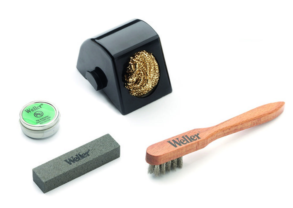
So we have to clean the tip. At first preferably in a dry way using brass wool, which is usually part of the solder handle holders. Alternatively, only in a very slightly moistened sponge.
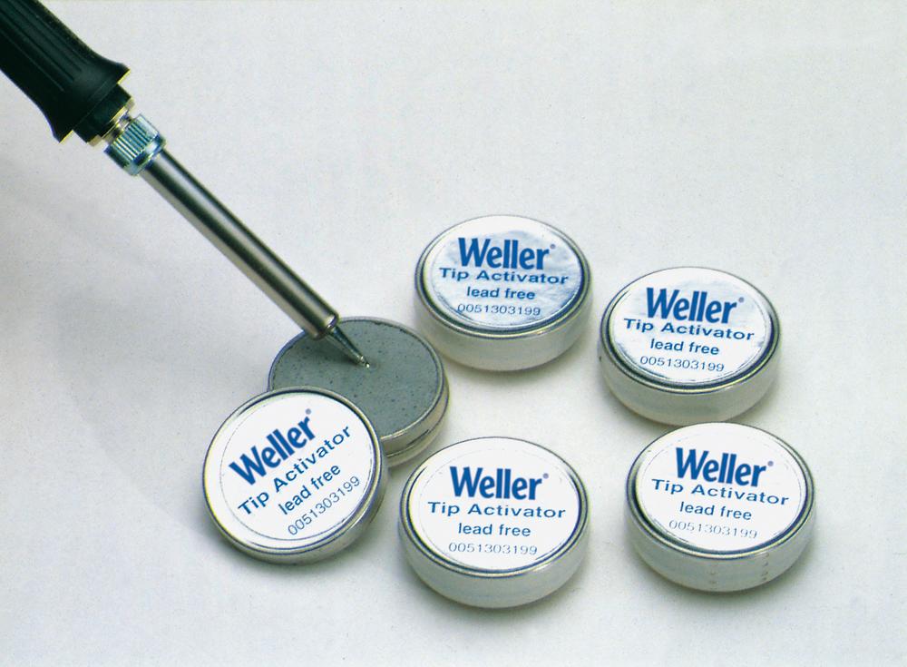
If your tip still isn’t clean you should try the so-called tip regenerator, e.g. Weller tip activator, which cleans and tins the tip in one step.
However, even these tip regenerators operate only to a certain degree of contamination. If the tip is very dirty, only gentle and careful mechanical cleaning will help. You can use special delicate brushes and abrasive stones, e.g. Weller WDC 2 kit.
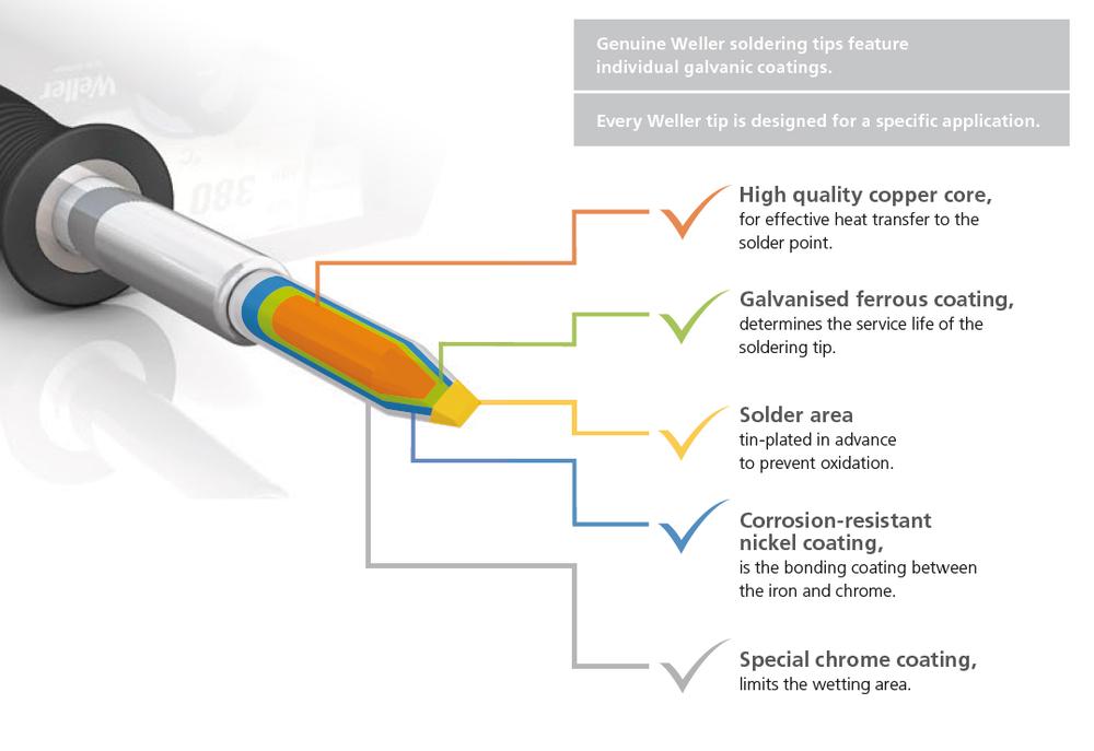
The core usually consists of copper and a layer of iron and then nickel. If the surface layer is damaged, or it even has a miniature recess in the tip, it can not be fixed. You need to buy a new one.
It is worth mentioning that the thickness of the nickel layer and the tip construction are quite different from various manufacturers.
Can I somehow prevent tip oxidation?
It is not possible to completely prevent it, but it can be significantly reduced. A simple and very effective method is to keep a little solder on the tip. This means that at any break in soldering when we put the handle into the rack, and we don´t turn off the soldering machine or we don´t switch to standby mode, it is good to apply some solder on tip. This solder will deteriorate within a few minutes but it will protect the tip. Just don´t forget to Before soldering you just need to clean the tip.
How long should I heat the circuit board?
A beginner and an amateur usually don’t care about time (length) of soldering and they have no problem soldering one joint for even up to 5-10 seconds. Of course, it’s very long. On the other hand, we often find pay-per-action operators, who get paid for the number of completed boards in a given time. These professionals often tend to shorten the time to a minimum, even below 1 second, usually at the cost of very high working temperatures which shortens tip and solder life, and moreover creates a high-temperature shock to the components.
True professionals already have their own well-proven process. For those less experienced, we can say that the recommended length of time for the tip to touch the joint is about 1.5-3 seconds.
If it is necessary to heat the connection noticeably longer, there is usually a low set temperature, or more likely an inappropriate tip/power for the given joint.
If we look at a typical temperature/time graph for reflow soldering, we find that SMT components can withstand quite a lot. And especially if we work mainly with SMT components, we can say that we can cause them more harm by the temperature shock from the too hot tip than a little longer soldering at a reasonable temperature.
What if I can’t get enough heat even from a short and thick tip?
Obviously, in that case, the heat supplied from the solder handle/station is not sufficient. In other words, you need a more powerful station/handle.
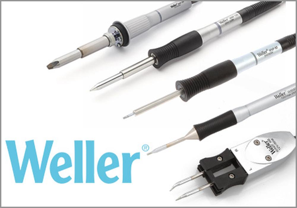
In practice, for example, there is quite a big difference between typical 80W tools (such as Weller WSP80) ) and 120 / 150W tools such as e.g. WXP120.
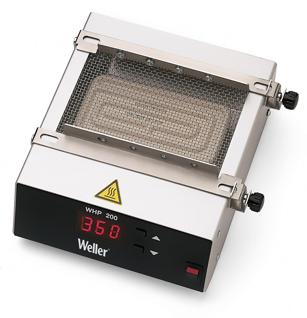
Here is another helpful device – use of the bottom heating plate. Thanks to the heating plate, we can heat the whole PCB to a certain temperature, safe for other components on a PCB and you don´t need such a performance from the soldering handle.
If we heat the board only to 100-120°C, we find out that we can easily solder earth-joints with a large area of copper around.
Besides, the heating plate reduces the thermal shock of components, making it a very convenient accessory for manual soldering.
What else can we do to prolong the lifetime of tips and soldering stations?
If the soldering iron offers this option, we recommend using a power saving mode (it decreases temperature) while not soldering.
When we, for example, reduce tip temperature during a break to 150 °C,in fact, we eliminate the formation of oxides during solder inactivity, while maintaining a sufficient temperature for the easier rise back to work temperature of about 350°C.
Some soldering irons use power monitoring for power-saving mode, some have a microswitch stand (such a stand can be purchased separately, for example, WDH10T), and the most modern have a state-of-the-art motion sensor in the handle (for example, the entire WX handle series and Weller WTP90).
If we meet these basic steps, we should achieve reliable joints without any problems:
- if the soldered surface is not ideal, it is possible to use more aggressive flux, but it will most likely be necessary to rinse the residues from the PCB
- use quality soldering station with reliable temperature measurement and good heat transfer from the heater to the tip
- choose a suitable solder with good metallic composition as well as content and type of flux
- solder only clean and non-oxidized surfaces/outlets
- original manufacturer’s tips are in the vast majority of cases better and more economical as a result of their longer life
- do not use excessively high soldering temperatures to compensate not ideal tip selection
- keep the soldering tip clean and always tinned
- in many cases, the heater plate (bottom heater) is almost a miracle aid for soldering problematic heat-demanding joints
- use the largest and shortest tip usable for a given type of joint
We believe that our insights will help you solder even better than before. If you have other questions that we have not mentioned in the article, we will be happy to advise you at [email protected] or we can train you directly as in the case of our customers.
“By training, we have gained a real overview of how individual manual tinning activities are linked. Demonstrations – causing too high temperature, too low solder temperature during tinning was a good example for our employees, and despite our long experience in tinning, we have been given a different perspective on tinning and therefore we hope to improve our performance process. ”Qess s.r.o.
“The operators were fully satisfied with the form and content of the training. Thanks to the training we managed to guide all the employees through soldering, operation, and maintenance of soldering stations. In our reports, we have seen a decrease of scrap due to cold junctions and short circuit. We have a lot of new staff since your visit and we are considering taking up this training so that we have the whole team back on one standard.” GE Energy Slovakia s.r.o.