
Robust circuit board interconnects increase capabilities and mobile performance
Robert Stanton, Director of Technology – Omnetics Connector Corporation
High density, portable, robotic, space and body-mounted electronics all share in similar requirements their design. Advanced electronic systems are rapidly evolving in their use of advance chip technologies from CMOS, and GaN, (Gallium Nitride), to MEMs technologies. These new chips are operating at significantly lower voltages, and their current draw is minute. Portable power sources range from extended-range micro-batteries to solar collection systems. Robotic assisted devices, such as exoskeletons and prosthetic hands, utilize body powered energy to direct signals to remote parts of the device. The circuits they drive are much less susceptible to high voltage breakdown voltages.
New sensors, detectors, injectors, and small motors for rugged mobility are designed to operate at micro-current and voltages to support this new era of highly compacted electronic modules.
Analog data is often converted to digital format while onboard the circuit chips to control and direct the new devices they are to operate.
Simultaneously, however, signal speed is climbing from 3 Gigabits per second, to 5 Gigabits/sec. and upward. New transducer sensors, such as EMG in myographic monitors, are mounted on the human body or similarly on robotic fingertips. They send micro and milliamp signals to and from the central control circuitry back inside the main module. Single board computers are replacing our older and larger stationary units so they can travel inside the newer robotic and autonomous technology of the day. Key to today’s high-density miniature electronics is designing and routing signals to and from the detection and operating functions of the circuit.
Often times they require micro-wire cabling and Micro or Nano-sized connectors to route the electronic data to and from these highly-
condensed data and processing modules.
In all, new systems are small and mighty but also are significantly more exposed to potentially higher levels of environmental abuse. Interconnection designers are planning ahead during the design cycle to insure the resilience and performance their systems serve the modules well. Often times, miniature strip connectors, specifically designed for high reliability applications, are selected because they fit well for both the mechanical and electrical requirements needed.
Interconnection design considerations for today’s higher density modules begin with knowing the signal content, data speed, impedance, potential crosstalk, noise or EMI sensitivity the system will be exposed to. One can benefit by checking data or signal speeds coming from the sensor system as well as the transmission rate output from the main module. Working with an interconnect specialist can help review key wire type, gauge, shielding and drain systems. Digital signals are dependent upon square-wave rise-time and matching the wiring impedance from the driver circuit to the cable. This has been proven over the years in RF coax technology and is now becoming critical as digital speeds increase. Some multiple digital signals are stacked upon one circuit with NRZ, (non-return to zero), voltage levels, (such as in PAM-4), and can be more susceptible to SNR, (signal to noise ratio), issues. This can be controlled with combinations of wire design, spacing and connector pin-out planning. More standard cable can easily handle gigabit signal transmission using differential pair wiring with a dedicated drain wire. The trio of wires are shielded separately from other wiring inside the cable and careful attention is paid with where and how the return-drain wire is connected to the driving circuit board.
The main circuit card that supports chips, storage and processors will have some critical layout considerations. Signal routing on the board and especially ground lines can be critical elements and will need direct and clear routing out to the connector interfacing the circuit board. A Micro or Nano-strip connector must often match those routing and spacing needs of the board. (Note; Having an extra connector pin or two for additional side-bar ground or return lines often saves a redesign phase in developing a system.) Many connector suppliers offer designs that include IPC standard pads and through-hole layout patterns; however, those standards are quite mature and newer boards may require tailored connector lead patterns to suit the application. Connector design and development companies that are exclusively focused miniaturized interconnection systems can offer rapid first-article connector-to-board designs that specifically meet new design patterns and specifications.
To assure rugged connector performance, designers are advised to begin with Military Specification levels established for Micro-d, (mil. Std. 83513), and or Nano-d, (mil. Std. 32135), as a good baseline. These two specifications were designed and written by a team of connector specialists from key military supply companies. The focus was to clearly define a wide range of applications in rugged and extreme environmental conditions experience in the defense industry. The reliability portion of the specifications is focused on issues such as the number of mates and de-mates and physical conditions such as shock and vibration, corrosion, and immersion. This set of specifications is easily used as a reliability check-list for newer connectors being developed today that are even smaller, lighter weight, or even going into deep space environments. Miniature strip connectors are a great example of this next level of need.
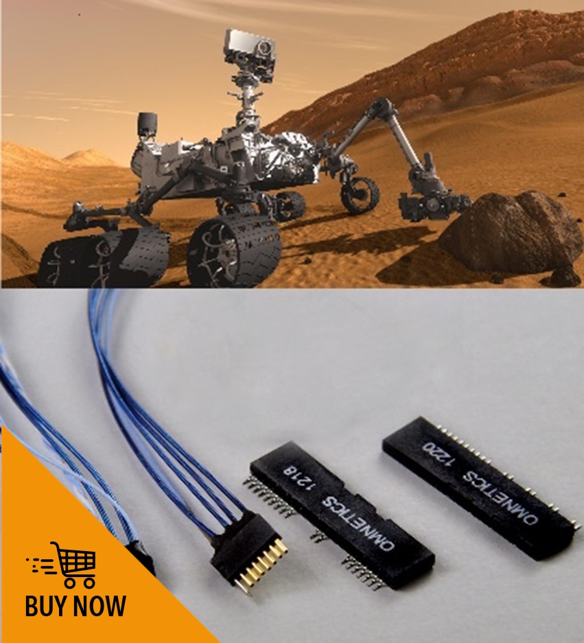
Strip connector suppliers appear to fall into two groups. The larger group is offering strips designed for the commercial market with limited testing and certification but quite useful for many applications. A more defined group of companies are using key materials and designs pulled from their own high-rel. military standard connectors. Companies, like Omnetics, uses their Military Specification solid BeCu (beryllium copper) spring pin and sockets that are plated with Mil. Specification Nickel and Gold to assure the highest reliability in the industry. Pin to socket mating and de-mating tests show constant signal integrity up beyond 2000 connections. These strip connectors offer rugged shock and vibration performance and have passed testing beyond the needs used in electronics sent to Mars. System designers can request sample strip connectors for a first test on their design. Micro-strip connectors at .050”, (1.27mm), pitch and Nano-strip connectors at .025”, (.635mm), spacing are established standards and readily available.
Also, designers can begin developing an adapted military-quality strip-connector with a connector designer using on-line solid modeling that is tailored to their exact application. When they are happy with the new design, a prototype sample can be requested to assure form, fit and function before proceeding. Imbedding your new interconnections with your circuitry early, allows a chance to test for signal, crosstalk and noise issues that can show up in the high density, low voltage circuitry we are employing today. When interested, designers can call for a couple of sample connectors for immediate inspection and review.
The final step in insuring the interconnect system meets the need for today’s new circuitry is testing and setting up any special quality standards required. By reviewing again, any unique environmental, or electrical specifications that may of concern, the designer is advised to talk to your supplier. Ask them for specific assurances, or tests.