In this article, learn about protecting three major base station systems, the baseband unit, the power supply, and the backup battery system.
Downtime is unacceptable in any communication system, and that certainly includes the new 5G cellphone communication systems.
Attaining high reliability often requires that the 5G macro base stations be robust to powerline surges and electrical disturbances such as lightning-induced transients and other transients and overloads.
In addition to potential damage originating on the power line, the base stations must be sturdy to environmental electrical hazards such as lightning and electrostatic discharge (ESD) strikes. Design engineers need to protect their 5G base stations from these electrical hazards to prevent damage to the bases station and avoid critical downtime.
In the previous article, we addressed the proper circuit protection for 5G macro base stations, including the recommended protection components in the surge protection device (SPD), tower-mounted amplifier, and advanced antenna system (AAS).
This article will focus on protecting three major base station systems, the:
- Baseband Unit
- Power Supply
- Backup Battery System
We’ll also aim to present component recommendations to protect circuits from electrical hazards and minimize power consumption, improving product life and reliability.
Protecting the Baseband Unit
The baseband unit processes data from calls and data transmissions and links data between the wireline infrastructure and the AAS. Additionally, this device either encodes transmissions or decodes received signals. Note that the baseband unit has its own power supply, as shown in Figure 1.
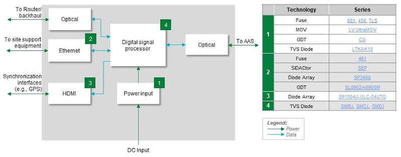
Power Input
On the input of the power input circuit, one solution is to use a fuse for overcurrent protection. Additionally, for this DC circuit, you could also consider using a fast-acting fuse. Surface mount fast-acting versions are available for space-saving applications.
A metal oxide varistor (MOV) and a gas discharge tube in series could also help protect the front-end of the power input circuit from transients that have passed through the main AC power supply, the power supply, and backup battery circuit.
Since the power input feeds all the other circuits, consider protecting these circuits from transients and ESD with a transient-voltage-suppression (TVS) diode, shown in Figure 2, at the back end of the power input circuit.

A TVS diode has a lower clamping voltage than a MOV and enables lower voltage-rated components in the downstream circuits.
Ethernet Circuit
When it comes to the Ethernet circuit, transient protection with crowbar protection components can protect the integrity of the Ethernet communication port.
If a Power-over-Ethernet (PoE) communication link is in use, consider a protection thyristor.
An alternative protection solution is using a TVS diode array and a gas discharge tube. A TVS diode can employ a Zener diode for clamping a transient compared with the protection thyristor, which crowbars the transient.
You can look for versions of these components with low capacitance to minimize the impact on the quality of the data transmissions.
Additionally, if the protocol is PoE, include a fuse to protect the Ethernet circuit from an overload resulting from crossed lines connecting to the circuit.
HDMI Circuit
As for HDMI circuits, HDMI interface data lines should have ESD protection.
Consider a 4-line TVS diode array, shown in Figure 3, to absorb ESD strikes up to 20 kV.
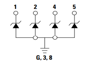
It’s important to look for components with low leakage currents below 50 nA and capacitance under 0.5 pF to minimize disturbance for high-speed HDMI transmissions.
Digital Signal Processor (DSP)
One important aspect to consider is the critical block in the baseband unit, the DSP. This device also should have voltage transient protection.
As with other circuits in the baseband unit, a TVS diode will provide either uni-directional or bi-directional ESD protection up to 30 kV.
Protecting the Power Supply and Backup Battery System
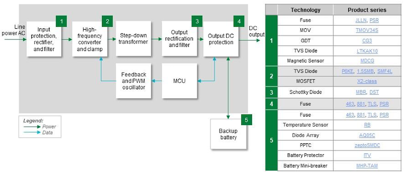
Overall, the power supply and backup battery system provide both AC line power and DC battery backup power to ensure the base station remains powered when AC line power is disabled. Figure 4 shows the circuit blocks of the power supply and backup battery system.
Protecting the Input Protection, Rectifier, and Filter Circuit
In a macro base station application, input protection, rectifier, and filter convert the AC input to DC. Since it interfaces with the AC line, it needs the full suite of overcurrent and overvoltage transient protection.
For current overload and short circuit protection, using a fast-acting fuse can prevent damage to the power semiconductors in the power supply. With this method, it is necessary to ensure that the selected fuse has a current rating to avoid nuisance failures due to the power supply’s inrush current.
Also, it is important that the fuse’s voltage rating exceeds the voltage on the AC line. The other power supply circuits can incorporate a MOV-gas discharge tube across the input line to absorb and protect the circuit from AC line-induced voltage transients. A TVS diode in the circuit is also recommended to increase immunity to transient surges and improve long-term reliability.
Finally, adding a magnetic sensor into the circuit can ensure the power supply is de-energized if a door on the electronics cabinet is opened.
High-Frequency Converter and Clamp Circuit
The high-frequency converter and clamp convert the rectified AC line voltage into a pulse waveform in the kHz frequency range.
A TVS diode can be used to absorb any transients that managed to pass through the input circuitry and protect the downstream circuitry.
To maximize the efficiency of the switching power supply, MOSFET with low Rds(on) and high dv/dt could be used to reduce on-state power consumption and switching power losses.
Output Rectification and Filter Circuit
The output rectification and filter convert the pulsed voltage back to DC voltage. One solution can be to use Schottky diode rectifiers with ultra-low forward voltage to reduce losses in the circuit. With the low forward voltage drop, Schottky diodes can contribute to an improved supply efficiency.
Output DC Protection Circuit
To help protect the power supply, one method is to utilize a fast-acting fuse in the output DC protection circuit. This solution could protect the power supply from any overload failures in the loads, including the AAS and the baseband unit.
Backup Battery
Finally, the backup battery is a high-power battery pack that can support the base station when AC power is interrupted. To help protect this device, it’s important to consider using a fast-acting fuse on the battery circuit for overload protection.
Also, monitoring battery temperature rise is necessary for ensuring the safety of the battery. For this, you could use surface mount thermistors placed on the battery pack modules. This method could also help protect the battery pack modules from overcharging.
An alternative solution could be a three-terminal device, which is available to detect an overvoltage condition and act as a fuse to disconnect the modules from the charging voltage. This component could replace the fast-acting fuse.
Another component that can be a backup to the battery management IC in the backup battery circuit is a mini-breaker that can be a switch paralleled with a polymer positive temperature coefficient component. This component provides both overtemperature and overcurrent protection to the battery pack, as well as providing a secondary protection component that helps to keep the battery pack from entering into an over-charge condition or an under-discharge condition.
Overall, the battery management system (BMS) in the backup battery circuit has voltage sense lines that connect to the individual cells of each battery pack. These sense lines are susceptible to ESD and other voltage transients. TVS diode arrays consisting of a package with two TVS diodes connected anode-to-anode on the sense lines for bipolar transient protection are recommended.
When the backup battery circuit uses the I2C communication protocol to transmit the status of the battery pack from the fuel gauge IC to the battery management IC, consider utilizing a polymer positive temperature coefficient component for limiting current on the I2C lines during a high voltage transient. This series component protects the overvoltage components that safely absorb transients on the I2C data lines.
Designing Base Stations for Maximum Uptime
All in all, communication infrastructure must have extremely high reliability so that uptime can exceed 99.9%. The recommended component technologies could help provide the high reliability needed for wireless communication infrastructure by protecting the circuitry from the five sources of electrical hazards.
There is a wide range of safety components and multiple versions of the components available to the designer. Designers can save development time by working with the component manufacturer’s application engineers to specify the required protection, control, and sensing components. Also, the application engineers can assist with guidance on meeting national and international standards for base stations. Some manufacturers also offer pre-compliance testing to help designers with standards compliance.
The bottom line: protecting a base station’s design from overload current and voltage transient hazards can be essential to ensure manufacturers deliver high-reliability equipment in the rapidly-growing 5G market.